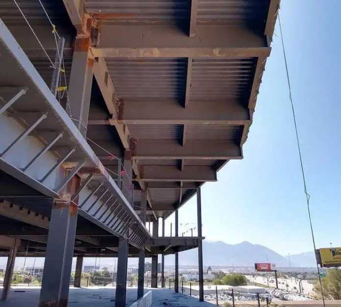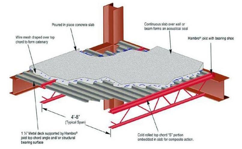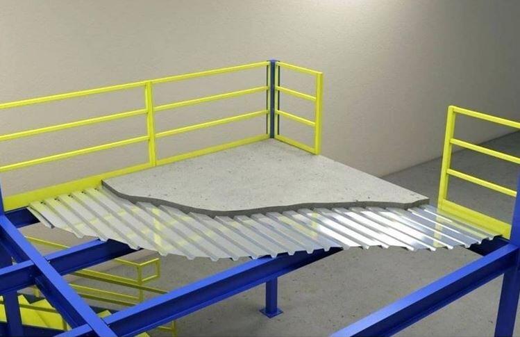

The general theory of composite beam design calculations is well known among structural engineers, however, the execution of composite beam design in practice necessitates taking into account a number of factors in addition to structural calculations, such as fire engineering, constructability, and more. This article discusses the structural design of composite beams and some of the factors that must be taken into account while designing composite beams.
The construction industry in the United States of America now uses two basic approaches to composite beam design – The LRFD and ASD methods. The method featured in the 3rd Edition LRFD Manual of Steel Construction is both simpler in design and more cost-effective than the method described in the 9th Edition Manual of Steel Construction (ASD).
In the ASD method, the moment capacity is computed from the superposition of elastic stresses, while in the LRFD approach, the moment capacity is computed from the distribution of plastic stresses.

It is usually possible to produce an economical design with partial composite action in the beam. In many design situations, increasing the beam size can satisfy the design moment while significantly reducing the number of studs needed. The design of composite beams is almost always carried out using computer software or design tools like those found in the AISC Manual.
The deck size should, within reason, be chosen to allow for the beam spacing. For un-shored construction, the Steel Deck Institute (SDI) offers tables that show the maximum span permitted for a specific deck and slab arrangement. In general, the economy of the steel floor system is improved by maximizing the span for a given deck size, for un-shored construction. It is advised that you choose a deck assuming a 2-span un-shored condition and avoid single-span situations as much as possible.
The ponding of concrete as well as how the slab is poured must be taken into account. You might want to factor in an extra 1/2 inch of concrete to accommodate for ponding when estimating the amount of concrete needed to construct level slabs. Since the wet weight of lightweight concrete has been reported in the field to range up to 125 pcf, it is crucial to consider this.
All of the approved ASTM material specifications for the construction of composite floors are included in Section A3 of the AISC Specification. During the design of composite beams, it is pertinent to always specify ASTM A992 when broad flange beams are being used. However, HSS, pipes, and built-up shapes are also covered by the AISC requirements. The ASTM A108 shear stud, which has a tensile strength of 60 ksi, is frequently used in specifications. 3/4-inch diameter studs are the most typical size used in building construction.

In addition to reinforcing bars and welded wire, the composite slab may also be steel fibre reinforced in accordance with ASTM C1116 in specific circumstances. For normal-weight concrete and light-weight concrete, the minimum specified compressive strength of the concrete in the slab must be between 3 ksi and 10 ksi. Higher strengths should only be relied upon for rigidity. In order to comply with standard fire-rated assemblies, 3.5 ksi normal-weight concrete and 3 ksi light-weight concrete are typically specified.
Although there are several ways to obtain level steel-framed floors, cambering of beams is the technique of choice in the United States. Engineers in the field frequently misunderstand the purposes of proper beam cambering. Beam camber is just one component of a comprehensive floor levelness strategy that must take into account the slab pour method, building occupancy, and steel fabrication and installation procedure.
The main objective of cambering beams is to accurately predict how much the beam will actually deflect under the weight of the concrete. Correct camber is best attained between 75 and 80 percent of the estimated dead load deflection because of connection restraints and fabrication tolerances. Beams should never have excessive camber. Additionally, cambering is improper for a variety of beam types, including brace beams and very short beams.
For composite floors, serviceability factors to be taken into account are long-term deflections from the superimposed dead load, short-term deflections from the live load, vibration control, and slab system performance. The acceptance standards relevant to the intended floor use, creep deflections under superimposed dead load, and partial composite action must all be taken into account when evaluating deflections.
The 1999 AISC Specification’s Section 15.6 addresses proper stud design and detailing. In the longitudinal and transverse directions, the minimum stud spacing is 6 times and 4 times the stud diameter, respectively. Two new factors—stud geometry and stud position inside the deck ribs—will need to be taken into account in accordance with the 2005 Specification.

Design a 25ft long secondary beam in a proposed commercial complex. The deck ribs are perpendicular to the beam, and the secondary beams are spaced at 10 ft intervals. The concrete for the steel deck has an overall depth of 6 inches with a compressive strength of 3 ksi. The following loadings are anticipated on the floor;
Weight of steel deck = 3.000 psf
Additional dead load= 20.000 psf
Weight of steel beam = 54.000 lb/ft
Weight of construction live load = 20.000 psf
Floor live load = 40.000 psf
Lightweight partition load = 10.000 psf

Basic dimensions
Beam span; L = 25.000 ft
Beam spacing on one side; b1 = 10.000 ft
Beam spacing on the other side; b2 = 10.000 ft
Deck orientation; Deck ribs perpendicular to beam

Profiles are assumed to meet all dimensional criteria in AISC 360-16
Overall depth of slab; t = 6.000 in
Height of ribs; hr = 1.500 in
Centers of ribs; ribccs = 6.000 in
Average width of rib; wr = 2.500 in
Concrete
Specified compressive strength of concrete; f’c = 3.00 ksi
Wet density of concrete; wcw = 150 lb/ft 3
Dry density of concrete; wcd = 130 lb/ft 3
Modulus of elasticity of concrete; Ec = wcd 1.5 × √(f’c × 1 ksi) /(1 lb/ft 3 ) 1.5 = 2567 ksi
Steel
Specified minimum yield stress of steel; Fy = 50 ksi
Modulus of elasticity of steel; ES = 29000 ksi
Weight of slab construction stage; wslab_constr = [t – hr × (1 – wr / ribccs)] × wcw = 64.062 psf
Weight of slab composite stage; wslab_comp = [t – hr × (1 – wr / ribccs)] × wcd = 55.521 psf
Weight of steel deck; wdeck = 3.000 psf
Additional dead load; wd_add = 20.000 psf
Weight of steel beam; wbeam_s = 54.000 lb/ft
Weight of construction live load; wconstr = 20.000 psf
Floor live load; wimp = 40.000 psf
Lightweight partition load; wpart = 10.000 psf
Total construction stage dead load;
wconstr_D = [(wslab_constr + wdeck + wd_add) × ((b1+b2)/2)] + wbeam_s = 924.625 lb/ft
Total construction stage live load;
wconstr_L = wconstr × (b1 + b2) / 2 = 200.000 lb/ft
Total composite stage dead load(excluding walls);
wcomp_D = [(wslab_comp + wdeck + wd_add + wserv) × (b1 + b2)/2] + wbeam_s = 839.208 lb/ft
Total composite stage live load;
wcomp_L = (wimp + wpart) × (b1 + b2)/2 = 500.000 lb/ft;
Max ultimate moment at construction stage;
Mconstr_u = ( 1.2wconstr_D + 1.6wconstr_L ) × L 2 / 8 = 111.684 kips_ft
Max ultimate shear at the construction stage;
Vconstr_u = ( 1.2wconstr_D + 1.6wconstr_L ) × L/2 = 17.869 kips
Maximum ultimate moment at the composite stage;
Mcomp_u = ( 1.2wcomp_D + 1.6wcomp_L ) × L 2 / 8 + 1.2 × ww_par × L 2 /8 + 1.2ww_perp × (b1 + b2)/2 × L/4 = 141.176 kips_ft
Maximum ultimate shear at the composite stage;
Vcomp_u = ( 1.2wcomp_D + 1.6wcomp_L ) × L/2 + 1.2 × ww_par × L/2 + 1.2ww_perp × (b1 + b2)/2 × 1/2= 22.588 kips
Point of max. B.M. from nearest support;
LBM_near = L/2 = 12.50 ft
Trial steel section; W10X54
Plastic modulus of steel section; Zx = 66.60 in 3
Elastic modulus of steel section; Sx = 60.00 in 3
Width to thickness ratio; λf = bf / ( 2tf ) = 8.130
Limiting width to thickness ratio (compact); λpf = 0.38 × √(ES / Fy) = 9.152
Limiting width to thickness ratio (non-compact); λrf = √(ES / Fy) = 24.083
Flange is compact
λw = h_to_tw = 21.200
Depth to thickness ratio (h/tw); λw = 21.200
Limiting depth to thickness ratio (compact); λpw= 3.76 × √(ES / Fy) = 90.553
Limiting depth to thickness ratio (noncompact); λrw= 5.70 × √(ES / Fy) = 137.274
Web is compact
Strength check at the construction stage for flexure
Plastic moment for steel section; Mp = FyZx = 277.500 kip_ft
Resistance factor for flexure; φb = 0.90
Design flexural strength of steel section alone;
Mconstr_n = fb × Mp = 249.750 kip_ft
Required flexural strength; Mconstr_u = 111.684 kip_ft
PASS – Beam bending at construction stage loading
Web area; Aw = d × tw = 3.737 in 2
Web plate buckling coefficient; kv = 5.34
Depth to thickness ratio (h/tw); λw = 21.200
Web shear coefficient; Cv1 = 1.00
Resistant factor for shear; φv = 1.0
Design shear strength; Vconstr_n = φv × (0.6Fy × Aw × Cv1) = 112.110 kips
Required shear strength; Vconstr_u = 17.869 kips
PASS – Beam shear at construction stage loading
Note – for non-uniform stud layouts a higher concentration of studs should be located towards the ends of the beam
Effective slab width of composite section;
b = min(L/8, b1/2) + min(L/8, b2/2) = 75.000 in
Effective area of concrete flange; Ac = b(t – hr) = 337.50 in 2
Diameter of shear stud; dia = 0.750 in
Length of shear stud after weld; Hs = 3.00 in
Specified tensile strength of shear stud; Fu = 65 ksi
Cross section area of one shear stud; Asc = π × dia 2 / 4 = 0.442 in 2
Maximum diameter permitted; diamax = 2.5 × tf = 1.537 in
PASS – Diameter of shear stud provided is OK
Point of max. B.M. from nearest support;
LBM_near = 12.50 ft
No. of ribs from points of zero to max moment;
ribnumbers = int(LBM_near /ribccs -1) = 24
No. of ribs with 1 stud per rib; Nr1 = 24
No. of ribs with 2 studs per rib; Nr2 = 0
No. of ribs with 3 studs per rib; Nr3 = 0
Total number of studs; Nprov = Nr1 + 2Nr2 + 3Nr3 = 24
Group effect factor for 1 stud per rib; Rg1 = 1.00
Group effect factor for 2 studs per rib; Rg2 = 0.85
Group effect factor for 3 studs per rib; Rg3 = 0.70
Value of emid-ht is less than 2 in (51 mm)
Position effect factor for deck perpendicular; Rp = 0.60
Nom. strength of one stud with 1 stud per rib;
Qn1 = min(0.5 × Asc × √(f’c × Ec) , Rg1 × Rp × Asc × Fu ) = 17.230 kips
Nom. strength of one stud with 2 studs per rib;
Qn2 = min(0.5 × Asc × √(f’c × Ec) , Rg2 × Rp × Asc × Fu ) = 14.645 kips
Nom. strength of one stud with 3 studs per rib;
Qn3 = min(0.5 × Asc × √(f’c × Ec) , Rg3 × Rp × Asc × Fu ) = 12.061 kips
Total strength of provided shear connectors;
Ssc = Nr1Qn1 + 2Nr2Qn2 + 3Nr3Qn3 = 413.51 kips
Resistance of concrete flange; Ccf = 0.85f’cAc = 860.625 kips
Resistance of steel beam; Tsb = AFy = 790.000 kips
Beam/slab interface shear force; C = min(Ccf, Tsb) = 790.000 kips
The strength of studs is less than the maximum interface shear force therefore partial composite action takes place
Strength check at partial composite action
Actual net tensile force; Vh = C = 790.000 kips
Assuming a plastic neutral axis (PNA) at the bottom of the steel beam flange.
Resultant compressive force at flange bottom;
Pyf = bf × tf × Fy = 307.500 kips
Net force at steel and concrete interface;
Cnet = Tsb – 2Pyf = 175.000 kips
PNA is in the flange of I Section
Shear connection force;
Fshear = Ssc = 413.51 kips
Total depth of concrete at full stress;
dc = Fshear / (0.85 × f’c × b) = 2.162 in
Depth of compression from top of the steel flange;
t’ = A / (2 × bf ) – 0.85f’c / Fybdc / (2 × bf ) = 0.376 in
Tension
Bottom flange component;
Fbf = Fybf × tf = 307.500 kips
Moment capacity of bottom flange;
Mbf = Fbf(d – (tf /2) – t’) = 241.285 kip_ft
Moment capacity of web;
Mweb = Fweb[((d – 2tf)/2)+ tf – t’] = 68.155 kip_ft
Moment capacity of top flange;
Mtf_t = Ftf_t (tf – t’)/2 = 1.185 kip_ft
Compression
Top flange component;
Ftf_c = Fybf × t’ = 188.244 kips
Moment capacity of top flange;
Mtf_c = Ftf_ct’/2 = 2.953 kip_ft
Concrete flange component;
Fcf = 0.85f’c × bdc = 413.512 kips
Moment capacity of concrete flange;
Mcf = Fcf(t – dc/2 + t’) = 182.476 kip_ft
Design flexural strength of beam;
Mcomp_n = fb( Mbf + Mweb + Mtf_t + Mtf_c + Mcf) = 446.450 kip_ft
Required flexural strength;
Mcomp_u = 141.176 kip_ft
PASS – Beam bending at partial composite stage
Check for shear
Design shear strength;
Vcomp_n = Vconstr_n = 112.110 kips
Required shear strength;
Vcomp_u = 22.588 kips
PASS – Beam shear at partial composite stage loading
Calculation of immediate construction stage deflection;
Deflection due to dead load;
Dshort_D = 5 × wconstr_D × L 4 / (384 × ES × Ix) = 0.9248 in
Amount of beam camber; Dcamber = 0.000 in
PASS – The camber is less than the construction stage dead load deflection
Deflection due to construction live load;
D2 = 5 × wconstr_L × L 4 / (384 × ES × Ix) = 0.2000 in
Net total construction stage deflection;
Dshort = Dshort_D + D2 – Dcamber = 1.125 in
For short-term loading:-
Depth of neutral axis from the top of concrete;
ys = [b(t – hr)/ns(t – hr)/2 + A(t + d/2)] / [b(t – hr)/ns + A]
ys = 5.294 in
Effective of inertia for partially composite;
Is_eff = 0.75[Ix + √(Fshear / C) × (Is – Ix)] = 688.9 in 4
Proportion of live load which is short term; rL_s = 67 %
Deflection due to short-term live load;
DL_s = 5rL_swcomp_LL 4 / (384ESIs_eff) = 0.1474 in
For long-term loading:
Long term concrete modulus as % of short term; rE_l = 50 %
Depth of neutral axis from top of concrete;
Effective moment of inertia for partially composite;
Il_eff = 0.75[Ix + √(Fshear / C)(Il – Ix)] = 563.6 in 4
Proportion of live load which is long term;
rL_l = 1 – rL_s = 33 %
Deflection due to long-term live load;
DL_l = 5 × rL_l ´ wcomp_L × L 4 / (384 × ES × Il_eff) = 0.0887 in
Long-term deflection due to superimposed dead load (after concrete has cured)
Wall parallel to span and superimposed dead;
D4 =5 × (wD_part) × L 4 / (384 × ES × Il_eff) = 0.0000 in
Wall perpendicular to span;
D5 =(ww_perp(b1+ b2) / 2) × L 3 / (48 × ES × Il_eff) = 0.0000 in
Combined deflections
Net total construction stage deflection;
Dshort = Dshort_D + D2 – Dcamber = 1.125 in
Net total long-term deflection;
Dlong = Dshort_D + DL_s + DL_l + D4 + D5 – Dcamber = 1.161 in
Combined short and long-term live load deflection;
Dlive = DL_s + DL_l = 0.236 in
Net long-term dead and superimposed dead deflection;
Ddead = Dshort_D +D4 + D5 – Dcamber = 0.925 in
Post composite deflection;
Dcomp = DL_s + DL_l + D4 + D5 = 0.236 in
Allowable max deflection;
DAllow = 1.250 in
PASS – Deflection less than allowable